
Recently, the weather here in Pittsburgh has become rather winter like. Not surprisingly, this cold has left me without much desire to toil in my unheated garage. It’s not that I don’t want to work on the bike, it’s thats working in subfreezing temperatures is not much fun. Additionally, being the holiday season, I’ve been doing holiday things instead of motorcycle things. All of this in mind, I have managed to make progress.
The biggest advancement I have made has been on the front of the bike. I had all the parts in hand at the beginning of November, though exact fitting of the FZR600 forks wasn’t exactly figured out. These things take time. They aren’t simple bolt together items. I started by getting all the parts together in one place. Before working on the wheel and axle I need the stem and head bearings to work together. For this I threw out the old bearings and races and started anew with All-Balls taper roller bearing setup. There is large list of bearings and triple clamp bearing swap information on the All-Balls website that proved very helpful. The taper bearings are a nice improvement over the old set and will provide a better feel to the front end. To mount the new bearing I had to remove what was left of the old bearings. It was a simple job with a hammer and punch. I then cleaned those surfaces and installed the new outer races.
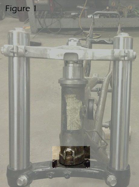
I was then able to start test fitting the triple clamp. The first obvious change was to shim the bottom head bearing up to accommodate the deeply inset race. Though, as room on the stem was limited I chose instead to simply remove approximately .0125″ off the bottom of the head bearing tube (figure 1). This allows the bottom triple to slide into the head tube without interfering with the frame. I also chopped off the non functioning steering stop while I was cutting down there. I then chucked the stem and lower triple in the lathe and got it trued up using the tailstock bearing. The big issues was throw on the lathe, the triple just cleared the lathe ways by maybe .1 of an inch, but that’s all I needed. Getting setup so the carriage didn’t hit either the chuck or the stem was tricky as well, but adjusting the cutting tool on the post allowed for the entire arrangement to finally work. You can press the stem out of the lower triple, but not having to saved me some time. I then just extended the upper bearing shoulder downward towards the bottom triple by about .65 of an inch. This finally gave me the ability to mount the triples to the frame.
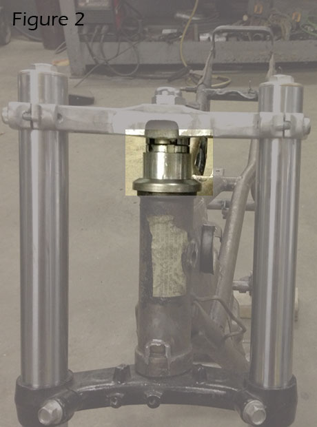
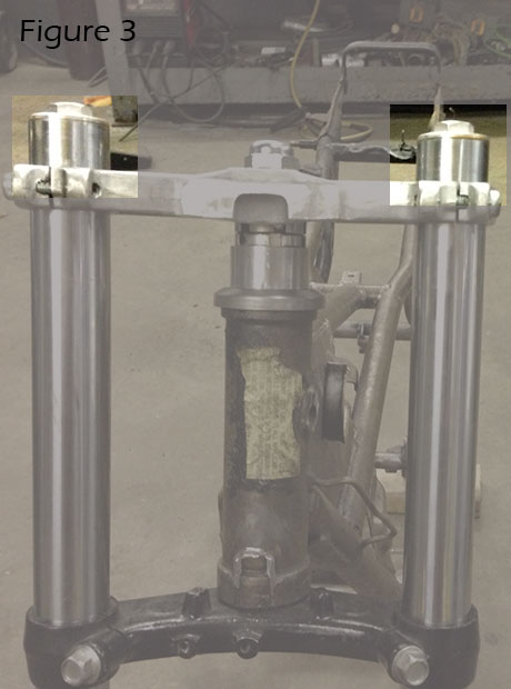
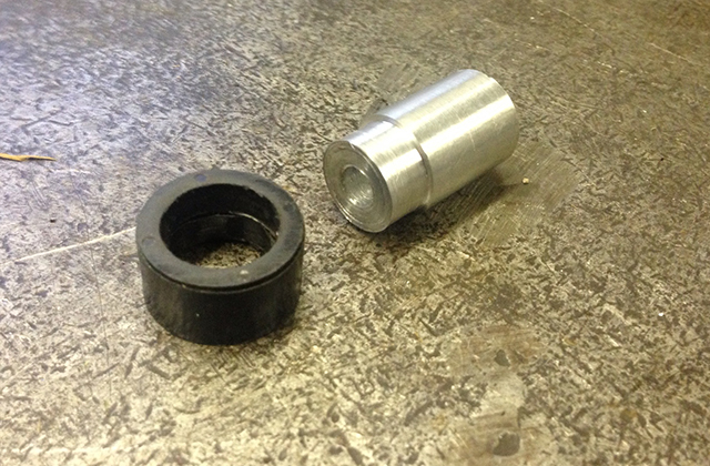
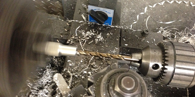
At this point all that was left was to make a spacer to account for the longer length of the FZR600 triple clamp stem (figure 2). I decided to stick with the longer length rather than shorten it. I did this so that I could achieve the proper triple clamp spacing on the forks. This helps maintain the proper amount of fork tube out the top of the top triple clamp. This also allows me to run my clip on bars above the triple clamp without a large amount of fork tube protruding above the clip ons (figure 3). Placing the clip ons above the top clamp should provide a more upright and hopefully more comfortable riding position while maintaining that low slung clip on bar look. The spacer needed to account for the shorter head tube on the RD frame. Luckily, there was a 2′ diameter 6061 aluminum solid bar drop in the bin by the lathe that appeared to be really close to the right height for this spacer. I chucked it up and began drilling. The outside diameter of the stem was 25mm, just short of one inch. I had a one inch drill bit on hand. I started small and after five or six different bits finally managed to get up to that one inch mark. Using a cutting tool I then faced both surfaces of the piece and tried it. Sure enough it pretty much exactly the right height. I never even measured it, but the entire assembly fit together flawlessly.
Adapting the front wheel to the forks required further reworking. The main obstacle was axle size. The RD350 uses a 17mm axle whereas the FZR utilizes a 15mm axle. One option was to source bearings that would fit the 15mm axle and have a corresponding outer diameter to fit the RD wheel. The other option I briefly explored was to make sleeves that would adapt the 15mm axle to the 17mm bearing, but considering the sleeve would have a 1mm wall thickness I decided otherwise. I settled upon building my own 17mm axle and boring the dropouts on the forks to match.
There were several reasons I chose to build a 17mm axle. Firstly, having researched the FZR forks rigorously, it was clear that many were dissatisfied with the performance of the 15mm axle. Secondly, a larger diameter but tubular axle should be able to provide greater stiffness a little or no weight penalty. Finally, the bike is going to feature lots of materials in their naked form and look. A stainless axle is a great addition.
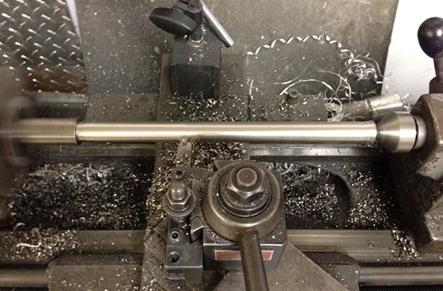
Cutting the axle meant several hours on the lathe. I bought 2 feet of material. I did not want to mess up the first time, but I would have extra material just in case. Cutting a piece twice takes way longer than cutting one, even if you really take your time on that first one. I chucked the bar up in the lathe and cut the face square. I then drilled a small pilot hole on the end so that I could use the tailstock center. At which point I marked out the width of the axle from what would be the head to end of the threads.
I used Stainless Steel 303. This grade of stainless is easy to machine and can be had for a reasonable price. Unfortunately my local materials shop did not have any decent drops so I resorted to McMaster Carr for my supply. I ordered the bar stock in .875″ as this would leave a large enough head on the axle while minimizing cutting. Though cutting 9 inches of material from .875″ down to .669″ is a fair amount of cutting nonetheless.
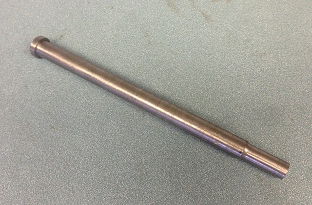
Once I had the length of the axle down to the 17mm diameter I cut a shoulder with an approximate 14.5mm diameter to accommodate threads. It was not a complicated item to make, but again, it was another time consuming project. I finished the axle by center drilling it. Unfortunately I do not have the tooling to fully center drill the axle end to end. As a result I left it about 60% drilled with the center of the axle remaining solid. If I had a small scale I would have weighed it, but I’m confident that it is lighter than the 15mm FZR axle while the math I did indicates that the axle should remain substantially stiffer.
The other big news is that I have finally finished my points replacement setup. There are at least two commonly used points replacement components on the market. The least expensive of which, and presumably the most popular, is the Dyna-S. It’s a very nice looking system and is sold over at VintageSmoke.com. The problem as I see it is cost. If you consider that you can buy a decent running RD350 for around $2k, the 300 dollar Dyna-S system is about 15% of the value of your entire bike. That’s a reasonable investment. In the four wheeled world, points replacement is very common. Specifically, Pertronix Ignitor systems are very popular.
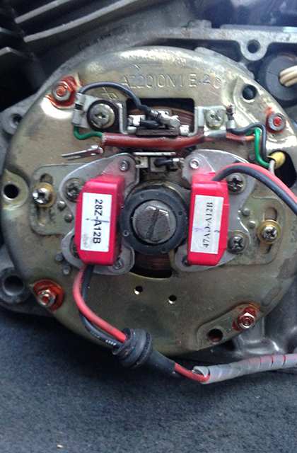
I did a fair amount of research on the use of the Pertronix on the RD’s and it seemed like it had been done in the past but never became popular. One thing seemed clear about the previous installations of the Pertonix. Whomever it was that was attempting the process was doing so in a method that used a single Ignitor pickup and two magnet rotor. This meant that the each cylinder was in a wasted spark scenario. In two-cycle engine terms that meant that the coils will fire each cylinder once at the bottom of the stroke and again at the top of the stroke. I have no experience with such scenarios, but my hunch is that it’s not desirable. Instead, I have configured my system with with two Ignitor pickups and a single magnet rotor. This fires each cylinder just once per revolution. The Pertronix configuration is just like the Dyna-S system in that you remove the entire points assembly including the condenser. Wiring the Ignitor is seamless as well and integrates directly into the existing wiring harness.
The first major benefits of the Pertonix is cost. I used two Pertronix Ignitor II units. These cost about $100 dollars a piece, so if I didn’t have the units laying around already I’d have saved myself $100 over the Dyna S. A second advantage, and perhaps the most important one, is that the Ignitor II has a function that will switch off the Ignitor pickup if the ignition is left on. If the engine is not started but the ignition is in the on position for long periods of time (2 or 3 minutes) both the Dyna-S system and the Ignitor I have a tendency to expire. It should be noted that a Ignitor I unit can be had for around 75 dollars. The downside of this system is that I had to adapt the entire Pertonix setup to the bike myself. This meant not only building brackets for the Ignitor pickups, which my father graciously took care of, but also cutting a hub for the magnet. These processes are elementary enough, but they did in fact take a significant amount of time. My first attempt is not prefect, though I believe it should work.
To finish points replacement I’ll need to set the timing. One of the biggest drawbacks of the Ignitor II vs. the Ignitor I is that static setup is almost impossible. The Ignitor II provides no visual references outside of general magnet location and the pickup. I have made a guess that places my spark somewhere before top dead center, but I won’t be able to set the timing properly until I can get a timing light on the bike. Timing adjustment will be done with a combination of moving the magnet on the rotor and fine tuning with adjustment at the pickups. Ultimately, this all requires the engine to be installed and the bike to be almost completely assembled so that a timing light can be used during engine operation. I plan to assemble the bike completely before painting/coating all of the parts. This will allow me to make final adjustments and alterations including the timing of the engine.
I also managed to get down and dirty with the RFY Shocks. These shocks are popular choices and show up often on builds all over the web. They look great, with visual cues very similar to Ohlins, and are extremely cheap ranging from $80 to $100 on eBay. I couldn’t pass them up, but wanted to do a good tear down and rebuild before trusting them with my life.
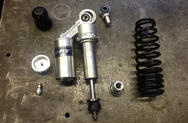
The assembly of the shocks is very much like an Ohlins. The gas bladder and shim stacks are pretty nice overall and the shock should work well once it is properly filled and purged of air. My major complaint about the shocks is the assembly. Mainly, they assemble these shocks with gobs of red Loctite, and I do mean gobs. I had to heat up the lower spring perch assembly with a torch to get the Loctite to ease up, even still I quite literally broke a sweat when unscrewing the perch. Once the spring was off, it takes a pin spanner to remove the nut the contains the shaft and seal. The big hurtle was removing the shaft seal. Excess Loctite had leached from bottom nut assembly and made getting the seal out nearly impossible. These mechanisms really shouldn’t be assembled with Loctite. They aren’t exposed to high vibration, so there just isn’t the need. Anti-seize compound is a much better solution. Considering that many of the parts are of dissimilar metals, anti-seize will not only promote proper torque but also inhibit corrosion.
Removing the bladder isn’t tough should you want to do it yourself, though tutelage from John Walko was required as I had never worked on this style of shock before. We clamped the shock in the vise at the eyelet on the reservoir end with the gas Schrader valve upward. We removed the Schrader valve, oddly it’s an English standard socket size, and using a wood block and hammer drove the bladder cap downward until we could get to the clip. With a small screw driver and some cajoling the clip came out. We then applied some compressed air to the bladder cap where the Schrader valve goes and that popped the cap off the bladder.

Interestingly, the shock castings have bosses where they would originally have had damping adjusters. This prompted me to do some digging on the origins of RFY shocks. It appears as though the shocks now designated RFY were originally Nicetect also called NCT (nicetect.com). I attempted to contact NCT but my emails have been returned undeliverable. Though I can not find NCT shocks for sale anywhere, thus I believe they have re-branded to RFY. NCT’s website shows shocks identical to these RFY models and also have more elaborate builds the include damping adjusters up to what looked like two-way adjustment. I have done some digging but haven’t been able to find the two-way adjustable models for sale at any online outlets. I’m going to keep up the hunt as a set of two-way adjustable shocks at Chinese prices would be fantastic, but until then this RFY set will be more than workable. When I reassemble them I will be using 10 weight oil and am confident they will be quality dampers.
That’s all for now, but up next will be frame modification. Be sure to stop back for more, but until then, happy holidays to all!
9 Responses
Jeremy Standiford
Dude, nice progress. I’ve always been curious about the RFY shocks too, thanks for the info! I bought some a set of progressives used for my KZ1000, but if they don’t work out I’m definitely getting a set of RFY.
Also, the high today in Albuquerque is 46 degrees. Makes me feel guilty for not working on my bike more in weather that you would consider tropical!
Chris
Thanks for posting! The RFY’s are such a good deal, I can’t believe that there is so little info out there on them. I hope to find the source of the better equipped Chinese units as well.
We had a good run of warm weather last week, it actually hit 63! People were wearing shorts and acting like it was summer. Today however the high was 21… Sigh.
Happy Holidays, Jeremy! Make sure to stop back.
Mike
Hi Chris. I’ve enjoyed reading your blog. Thanks for sharing all the info on these RFY shocks – It’s been really useful.
I’ve just ordered a pair for my bike and I’ll attempt to rebuild them myself. Can you let me know the size of the indents on the seal nut? Then I can get started making a tool like yours while I’m waiting for delivery.
Thanks!
Chris
Hi Mike!
I have an adjustable spanner that I made using a crescent wrench. I believe it uses 10/32″ bolts for the pins, though that may be too large. I’ll try to remember to measure those with my micrometer sometime this weekend.
Regards,
Chris
Mike
Great, that would be really helpful.
I saw your home-made tool, it’s an excellent idea. I’ll be copying that!!
Thanks again!
Butch Erwin
Chris, good write up. Have you found a source for the seals on the RFY’s? I have been looking everywhere, and have, yet, to find one.
Chris
Hi Butch,
Thanks! I have not found seals yet. They are odd, as I’m sure you are aware. If you get any leads, please let me know.
Regards,
Chris
Butch Erwin
There is a supplier called Canton ECO Auto in China that have what looks to be the correct seal. I have emailed them to see if there is a distributor stateside, or if they can be purchased directly. I will let you know what happens….
Chris
Great info, Butch! Keep me in the loop!