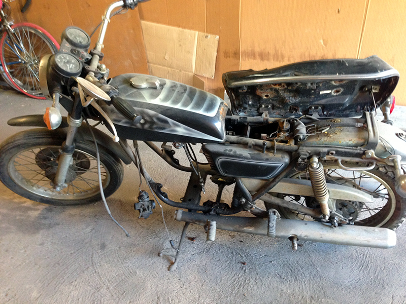
I think back to what the bike was like in September when I picked it up, it was a complete basket case. I can’t believe that this project has come this far. Right now, it’s just a bunch of parts spread out across two garages. Even still, it’s tough to believe that the parts I have now even came from that bike from four months ago. On the other hand, it’s also hard to comprehend how far I have to go before all of these bits will be a working bike. My blog posts concerning this build are approaching 15,000 words in total. A full length novel is considered around 80,000 words and a novella is about 40,000 words. I might make novella status by the end of this build!
That said, I have continued to make progress. My RFY shocks are now completely rebuilt. They have been completely torn down to their individual bits, inspected, and rebuilt properly. The front wheel is fully mounted to the FZR600 forks and adapting a caliper has begun. It’s a problem, one that I’ll focus on more once I assemble the bike for final test fitting before coating.
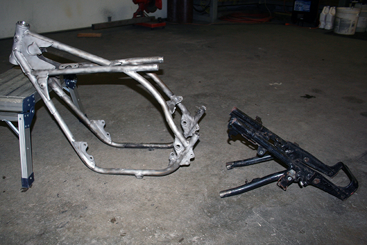
The big news is the rear sub-frame. What rear sub-frame you ask? The sawzall slipped when I was removing all of the extraneous brackets and I accidentally cut the existing rear structure off. While I was at it I may have accidentally ordered about ten feet of 6061 Aluminum tubing that John Walko and I will use to replace the aforementioned rear structure. Not only should the use of aluminum allow for a reduction in mass, it’s another addition to the growing list of corrosion resistant materials on the bike.
Choosing material to build the rear sub frame required consideration. The replacement structure needed to be equal in strength to the original, but to reap the benefits of aluminum needed to also reduce weight. The stock tubing is 25mm (about 1 inch) and the math seemed to indicate that I’d have to increase wall thickness dramatically on aluminum of a similar diameter to even come close to the steels strength. However, by increasing tubing diameter the aluminum would better be able to match the existing steel structure. Much like an aluminum bicycle, the rear sub frame will be produced of thin wall but large diameter tubing.
Before purchasing tubing I consulted my good friend, Garret Huff, who is a professional real life engineer. After the collaboration, it was decided that 1.5 inch diameter tubing would be adequate to replace the existing 1 inch structure. Whereas 1.25 inch tubing for the diagonals should do the job. By doing so I also hope to achieve an acceptable fatigue limit on the structure, though the math on this topic is difficult for me to properly parse. Suffice it to say, I think I’ve come to a good solution, but should the structure fail for one reason or another it will be easy to replace due to its modular nature. In the mean time I am working to model the rear subframe in CAD programming. Not that it will change my attempt this time around, but because I’m a nerd.
The added diameter of the horizontal tubing will also be used to create storage space beneath the seat. Placing a pan on the bottom of the tubes will create a floor and the seat will rest above the tubes. This means the cavity depth will be 1.5 inches, more than enough to store some things. This space will house the battery, the regulator-rectifier, as well as wiring and other miscellaneous objects that the bike requires.
The sawzall made short work of many of the now useless brackets and tabs. A frame brace and kickstand tab were removed. That kickstand tab will move and the brace will be replaced with a piece of thin wall aero-tube. Once I got through the major hacking and cutting I was to the point where I could start thinking about fabrication the subframe.
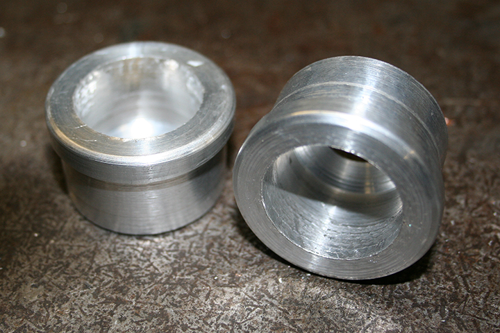
I first had to parse out a good method of mounting the rear sub frame to the existing structure. Despite that the creation of the subframe is in fact adding complexity, utilizing the frames vestigial bits helps simplify the process somewhat. I wanted the horizontal tube to slide over the remaing tubes but needed to make up for the difference between the 1 inch tube and 1.36 inside diamter of the new aluminum tubing. I accomplished this by making caps that fit in the end of new tubes. To make the caps I went back to the lathe. They will be welded into the aluminum tubes and fit tightly over the vestigial bits. To finish the mounting, a bolt will be placed vertically through the tube, the mounting cap, and the steel of the old structure. This places the bolt in double shear and should provide ample material and strength.
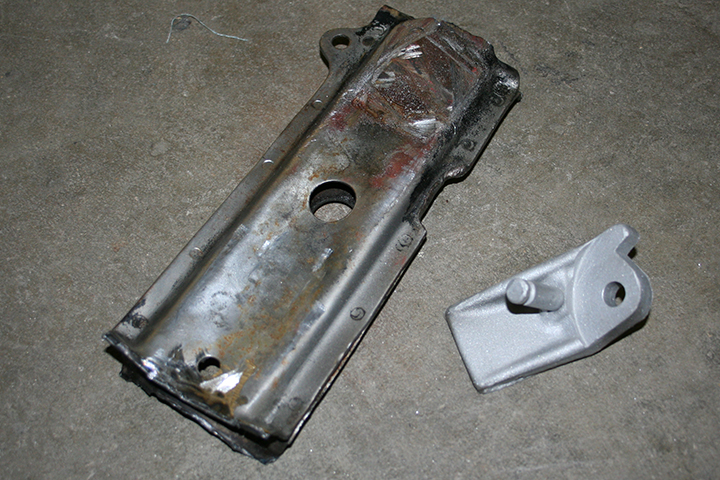
Once the upper mounts were figured out I was left with mounting the diagonals. After about 5 minutes of discussion with John the design became clear. The diagonal itself will have an attachment made by welding a hard point to it’s base. The hard point was fashioned out 1.25 bar stock and only required being center drilled for a bolt. The tube was notched to accommodate the hard points appropriately. I took no pictures of this part of the process, frankly, they are pretty boring pieces to look at. On the frame, we will fabricate a sheet metal box that will receive the tube and hard point. It will be fixed with a bolt in double shear. There’s is a giant amount of work b efore the subframe is completed. I still need to create several hard-points and device the final structures dimension. All these things will wait until my next post.
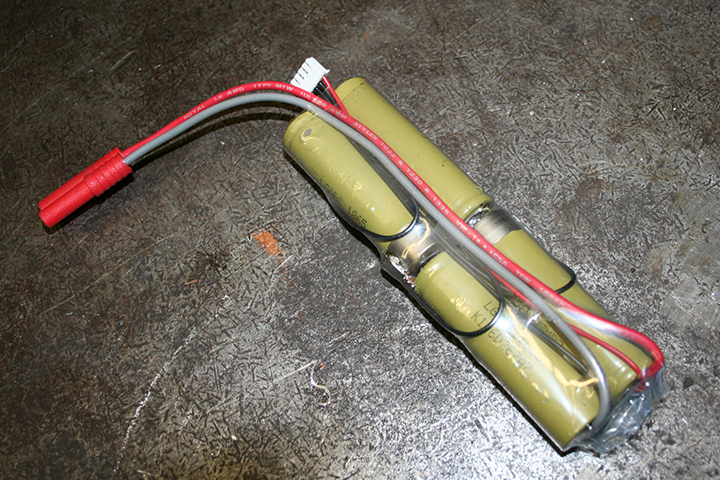
I managed a few other slick projects in the mean time. I finally got my ultra tiny battery finished up. If you missed my previous post on the battery, it uses four laptop Litium-Ion batterys wired in series to provide the 12 Volts that the bike requires. Since the bike has no electric starter and will be converted almost entirely to LED lights, the battery should be more than enough to run the system. I have also included in the battery a 4S balance plug which will allow me to balance charge each individual cell assuring maximum efficiency and life. For the main leads, I soldered in the bullet connectors using fancy aircraft grade wire. I wrapped the battery in a nice clear heat shrink to show case my less than stellar soldering ability. If the battery works as I predict, I will eventually go one step further and buy new batteries as well as proper battery tabs to build the pack. For now, it will have to do.
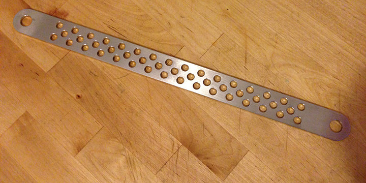
For Christmas I picked up a stainless steel brake rode from the user JSpooner over at the 2StrokeWorld.com forum. You’ve got to pick your battles with a project like this, and there was no doubt it would have taken a big effort to match the quality of JSpooner’s part. Not only is it stainless, but it looks great too. It’s obviously laser cut and it came out perfect. If I had spent hours at the drill press I couldn’t have come even close. Money well spent.
The final bit of progress I made was on the forks. I received a set of fork cartridge emulators for Christmas from my girlfriend. Installation was not difficult, but the process was time consuming. I first disassembled the forks almost entirely. This allowed me to clean the forks thoroughly. The oil that came out of the now 20 year old FZR600 forks was pretty dirty looking and it smelled especially bad. I stuck the forks and bits in the cleaning tanks and brushed all parts lightly with a paint brush while rinsing with mineral spirits. This removed the remaining fork oil out and off of the forks as best as possible.

To install the emulators I had to drill the damping rod. I drilled out the existing damping holes and created four more. This allows the fork oil to move through the damping rod easily. The emulators then add damping via a set of shim stacks just like a shock would. These allows me to adjust the preload on the spring to change the damping property of the forks. This was not a tough process but care was taken to ensure that no burrs were left behind. Once this was one I just had to reassemble the each fork. I filled them with 15 weight Maxima fork oil leaving a 13 centimeters of air space at the top of the fork. I am excited to try these babies out. The front end should be superb on this bike.
Next time around I plan to wrap up the rear subframe and build the seat. Make sure to comment below if you have questions. Thanks for reading!
Leave a Reply