With racing season coming, I haven’t had as much time as I did to work on the bike. I have a number other projects that I am currently working on, but I still have made a fair amount of progress. Mainly, after weeks of speculation and contemplating the subframe is almost complete. Building it was as much a matter of art as it was science. Also, I am going to take a small departure from my normal style of publishing this post. Typically, I place the photos as thumbnails down the left side of the page. Because a lot of this work is tough to describe and/or boring to read about, I feel bigger pictures will just be better.
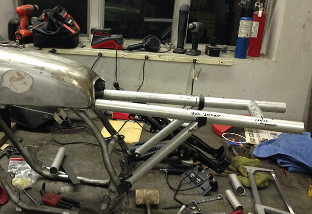
I spent a fair amount of time mocking up the design. It wasn’t hard to understand what the frame needed to do, but getting all dimensions correct the first time around would be a challenge. To create the mock-up, I left all tubes on the long side and then carefully went about cutting and modifying to get to the final product. Above is one picture of a very early mock-up.
While making the parts I spent a lot of time at the Bridgeport mill. I am a beginner at using the mill and it took me longer to get the mill setup correctly than it did to create the holes that I used it for. The use of the mill though was priceless for me. Not only was it a great experience, but I managed to produce some really high quality parts.
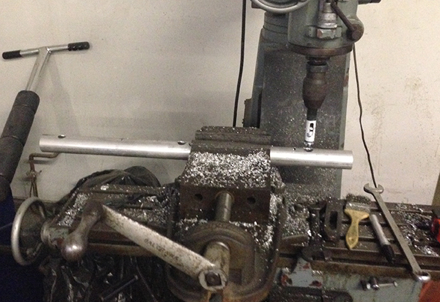
Above you can see one of the horizontal tubes in the mill. As a top tube, it is one of the two tubes that the seat will rest upon. Altering any of the tubes would be difficult once they are welded together, thus I had to make sure that they were right before hand. I also tried to anticipate a mode by which I could mount the seat securely to the tubes. The method I settled upon is fairly simple. I placed center drilled hard points in the top frame rail. To make these, I used the mill and a 3/4 inch hole saw. The above photo shows how the three holes were cut. The hard points were created using 3/4 inch aluminum bar stock that I center drilled on the lathe. The seat pan will mount to these hard points and should be extremely secure. This method also eliminates bulky fasteners and unsightly tabs or brackets.
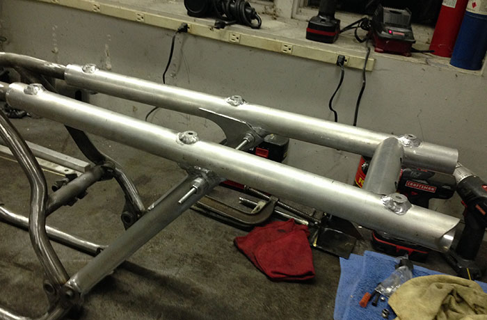
Above you can see the seat hard points are welded in the horizontal tubes. I will use quick release pins that go up through the hard points and into the seat pan to secure the seat. This will allow me to quickly remove the seat pan to access the battery, data acquisition systems, wiring harness, and in the future I’ll place the oil tank in there as well.
Also in the picture above you can see that the vertical tubes are welded to the horizontals. This required further work on the fitting of the tubes, most of which I performed with a file. Initial fitting was done with a tubing “notcher,” but further work was required to get a high quality interface.
The final piece of the puzzle was the gusset. I worked hard to get the tubes to fit tightly where they met each other, but a gusset would add additional strength. The gusset also supports the inside end of the shock hard points. This allowed me to adjust the shock hard point location after the sub-frame was mostly welded, assuring that the hard points would be properly aligned. The welds came out really nice and there is no doubt that the frame is stiff. As my hands aren’t nearly steady enough, John Walko did all of the welding for me. I can’t thank him enough, without his welding skill and the use of his machine shop this project would not have been possible.
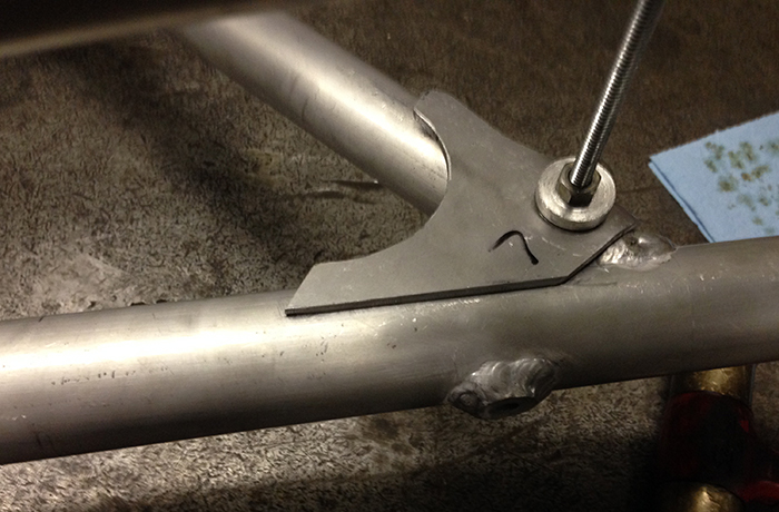
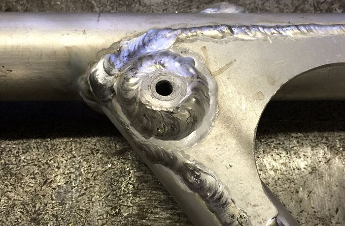
In the photo above you can see how closely the gusset fits to the hard point. This was required as the gusset largely supports the hard point. The gusset also provides a large amount of area to be welded to the frame tubes. This adds significant strength to the frame. Below, there is a close-up photo of the gusset in its welded form. The hard point also takes shape.
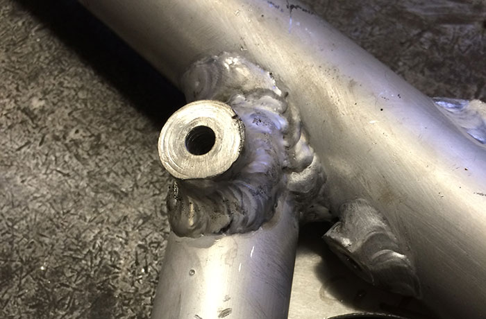
Below is a good shot of the shock mount from the exterior. A bolt will go through the shock eyelet and into this hard point. Before being complete though I will likely have to make a bolt to do this, and I will also have to thread the hard point to accommodate that bolt. It shouldn’t be tough, but it is a few more hours of work that needs to be completed.
The subframe is not completely welded, but it is 90% there. The cross member, which you can see in the mock-up photo above, will not be welded until the subframe is ready for final assembly. During this process I also fabricated other bits and pieces, but I’ll talk about those in later episodes.
Now that the rear subframe is very nearly done, I get to move onto test assembly. This will occur in the coming weeks and should be an exciting time in the build. Stay tuned!
Leave a Reply